


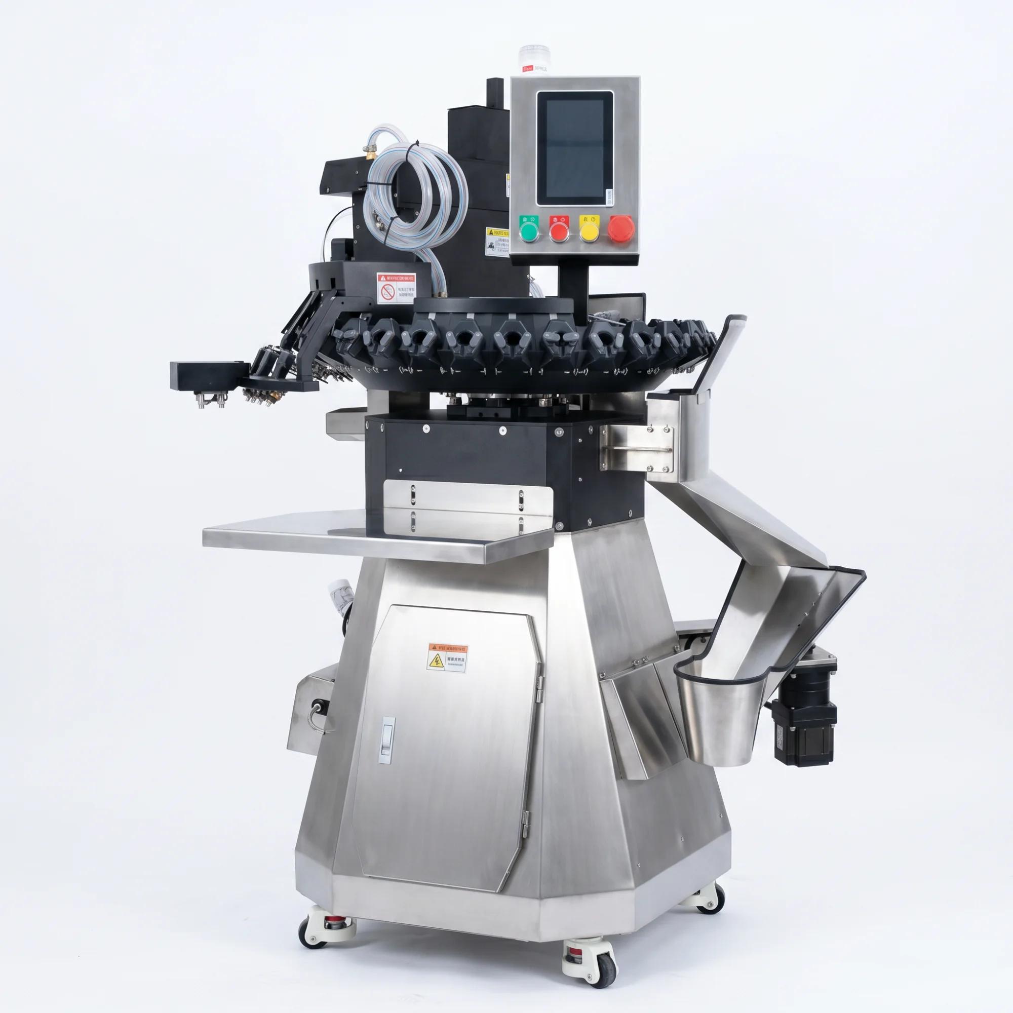
A chick processing line layout design can look tidy on a floor plan and still be difficult to operate. Equipment rectangles may fit while people, containers, supplies, cleaning tools, maintenance access, utilities, and stopped work compete for the same space. Seven transparent overlays help the project team see these conflicts before installation.
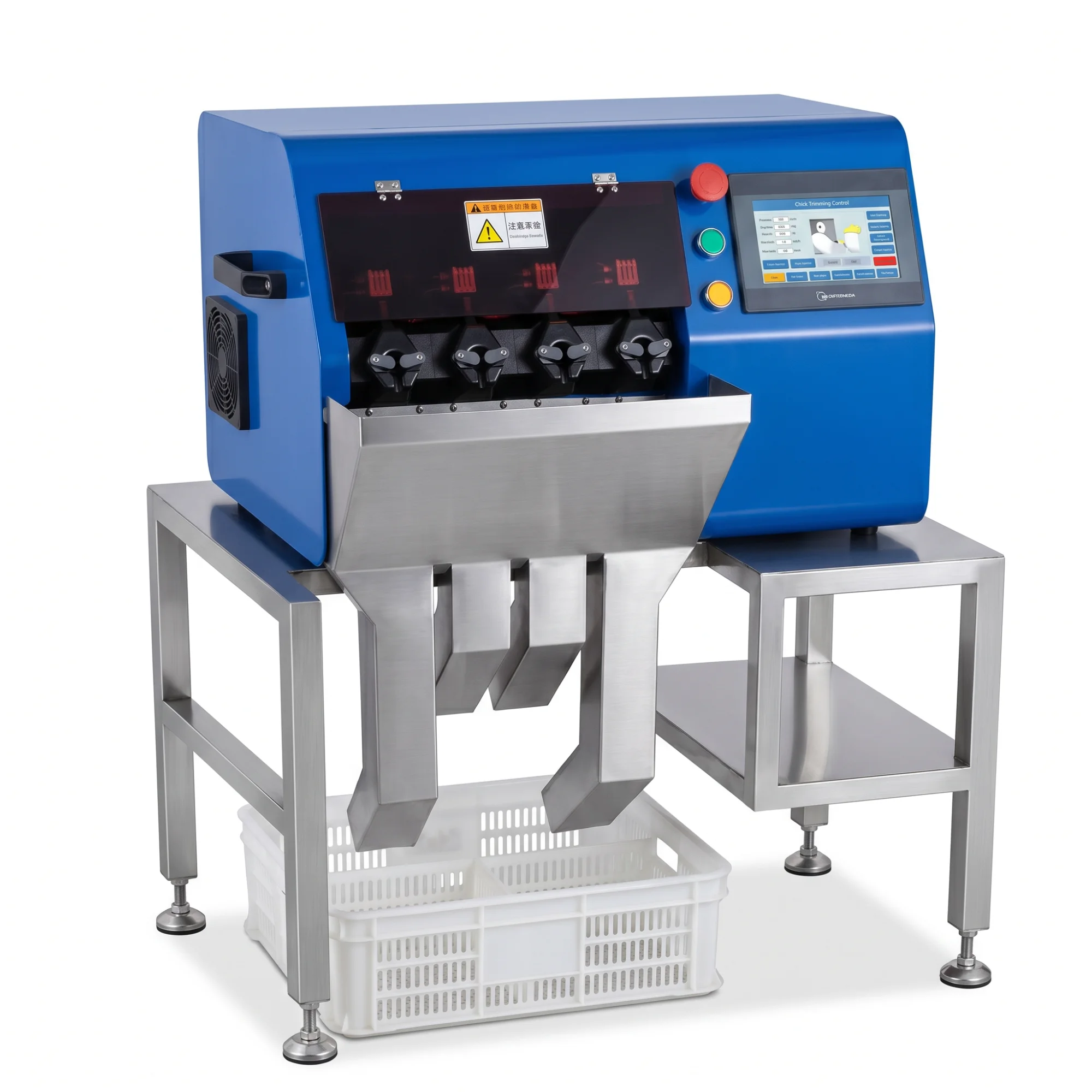
JuliSense provides standalone equipment and integrated hatchery automation solutions. Bring the overlays to a layout discussion so the equipment proposal reflects the real room and operating day.
Overlay 1: The Product and Container Route
Draw movement from arrival through processing, treatment or vaccination where applicable, counting, loading, conveying, stacking, and dispatch. Add empty and returned containers too.
Mark direction and identity
Show where loads are identified, released, transferred, accumulated, and handed to the next team. Avoid crossings that make status ambiguous.
Add peak arrival patterns
The route should handle normal variation without creating uncontrolled waiting. A chick processing line layout design needs the busiest interval, not only daily volume.
Overlay 2: Operator Work
Place every normal position, reach, repeated walk, supply point, control, record, and communication step on the plan. Then add breaks and shift handover.
Protect working space
Do not count the same floor area as both operator space and container staging. Mark the space needed for posture, movement, and authorized intervention.
Put information where decisions happen
Controls and messages should be visible from the position responsible for the action. A remote screen cannot compensate for unclear local ownership.
Overlay 3: Sanitation and Material Separation
Draw clean supplies, used items, waste, tools, water or moisture boundaries where relevant, and the route used after production. This overlay often conflicts with the shortest production path.
Review access after shutdown
Open guards and access panels on the drawing. Mark removable parts, cleaning positions, temporary placement, inspection, drainage, and release responsibility.
Keep the procedure customer-owned
JuliSense can explain equipment materials, access, removal, and limitations. The hatchery's approved program defines methods, agents, verification, and release. WOAH standards and codes provide international reference material.
Overlay 4: Maintenance and Replacement
Draw isolation points, diagnostic access, lubrication or inspection positions where applicable, tool clearance, lifting needs, and the route for removing a component.
Test the largest replacement path
The component may fit in place but not through the surrounding equipment, guard, door, or aisle. Confirm removal space in three dimensions.
Separate routine and specialist work
Identify tasks expected from site maintenance and those requiring supplier or specialist support. This helps the chick processing line layout design protect practical access.
Overlay 5: Utilities and the Building
Add electrical supply, compressed air, network connections, drainage where relevant, columns, doors, ceilings, floor changes, traffic, and emergency access.
Draw utility ownership
Mark connection points and responsibility for local routing, supports, protection, testing, and final connection. “By customer” should be detailed enough to price and schedule.
Review the delivery route
Trace equipment from unloading to final position. Include dimensions, weight information provided by the supplier, lifting points, temporary storage, doors, turns, and installation sequence.
Overlay 6: Stop and Recovery
Shade each control zone and show what happens when the next zone is unavailable. Draw committed loads, buffers, operator access, messages, restart order, and escalation.
Follow one blocked handoff
Choose a representative interface and stop it safely during review. Ask where every already released load goes and who decides the next action.
Keep recovery from creating a second problem
A bypass or manual removal route needs space, authority, identification, and a return method. The chick processing line layout design should show exception movement, not only normal arrows.
ISO 12100 provides a general machinery risk-assessment and risk-reduction framework. Apply the requirements relevant to the final installed system.
Overlay 7: Future Change
Draw the likely next module, parallel position, additional utility demand, control connection, and room access. Future planning should reserve sensible options without buying unused complexity.
Define the expansion trigger
Use measured peak demand, repeated bottlenecks, staffing constraints, or a confirmed program change. “We may grow” is too vague for a design decision.
Protect today's operation
An expansion provision should not make current cleaning, access, or controls harder. Mark what remains capped, reserved, or excluded in the first phase.
Resolve Conflicts on One Review Sheet
| Conflict | Example | Decision owner | Required evidence |
|---|---|---|---|
| Flow vs access | Staging blocks maintenance door | Engineering/operations | Revised layout |
| Production vs sanitation | Supply route crosses used-item route | Technical owner | Approved route |
| Equipment vs building | Guard opens into column | Supplier/site | Elevation drawing |
| Normal vs stopped flow | Buffer blocks operator aisle | Controls/operations | Stop rehearsal |
| Current vs future | Expansion removes cleaning access | Project sponsor | Phase plan |
How detailed should the first layout be?
It should be detailed enough to expose route, access, interface, utility, and building risks while clearly marking assumptions. Do not present an early concept as a released fabrication drawing.
Who should attend the review?
Include production, engineering, maintenance, sanitation or quality owners, technical or welfare owners where relevant, procurement, project management, and the equipment supplier.
What should buyers send JuliSense?
Share a scaled room plan, photos where permitted, batch and container data, current equipment, utility information, traffic, approved process requirements, selected modules, and future phases.
Test the Overlays With Three Room Scenarios
One static review can miss conflicts that appear only when the room changes state. Use three scenarios: peak production, a controlled downstream stop, and post-production cleaning or maintenance. Keep the same floor plan and switch the overlays that matter.
For peak production, add the largest expected staging, normal operator positions, supply replenishment, empty-container return, and dispatch activity. Confirm that aisles, controls, doors, and technical observation remain usable. This scenario tests whether the chick processing line layout design protects work during the busiest interval rather than only at steady average flow.
For the stop scenario, shade unavailable zones and trace every load already released. Mark buffer limits, operator messages, manual or controlled removal points, escalation, and restart order. Pay attention to places where temporary work occupies access intended for maintenance or emergency response.
For cleaning or maintenance, remove production assumptions. Open access panels and guards on the drawing, place tools and removed parts, show clean and used material routes, and trace the largest component replacement path. Confirm that temporary placement does not block isolation points or exit routes.
The three scenarios should produce a short conflict log. Each item needs the affected overlay, impact, proposed change, owner, drawing revision, evidence, and approval. Avoid solving every issue with another sensor or control function; a clearer physical route may be simpler to operate and maintain.
When should the layout be frozen?
Freeze it after critical routes, interfaces, utilities, access, building inputs, and customer requirements are confirmed. Keep unresolved low-impact items visible with owners rather than pretending the drawing is complete.
What belongs in the final layout pack?
Include the approved plan and elevations, equipment list, interface register, utility points, access zones, control-zone map, container data, customer work, supplier work, exclusions, installation sequence, and future provisions.
How should the supplier use the pack?
The supplier should connect equipment drawings, fabrication release, testing, installation, and commissioning back to the approved pack. This keeps the chick processing line layout design from drifting through separate documents.
One Floor Plan Is Not Enough
A robust chick processing line layout design becomes clearer as each overlay is added. JuliSense can discuss the equipment route through its products, automation services, and contact page. Before approval, make the chick processing line layout design readable to the people who will operate, clean, maintain, and expand the line.